


A profile rail guide provides precise and smooth linear motion while accommodating forces and moment loads. However, the required performance can only be achieved when the system is professionally installed and correctly aligned.
Incorrect installation can therefore lead to additional internal stresses, increased running resistance and premature wear of the rolling elements. To ensure the mechanical service life of the guide system, it is important to follow the manufacturer’s installation guidelines and carefully check the alignment.
Preparation and requirements for the mounting surface
Correct installation of a profile rail guide starts with a thorough inspection of the mounting surface. The mounting bed of the machine frame must meet the requirements for parallelism and height deviation associated with the selected rail type and carriage preload. The exact tolerances depend on the specific design and are determined based on the THK catalogue or advice from LM Systems. A higher preload generally requires a more accurately machined mounting surface to prevent additional internal stresses and increased friction.
Before installation, the mounting surfaces must be thoroughly cleaned. Dust, metal chips, oil, rust and burrs can prevent the rail from seating evenly. The profile rail guide itself must also be cleaned so that the corrosion-protection oil used during storage is removed before the rail is placed on the machine bed.
For mechanical fastening, THK specifies the use of strength class 12.9 bolts. THK’s dynamic load ratings are based on the use of these bolts. When fastening the rail, the bolts must be tightened to the correct torque in accordance with THK documentation. A suitable torque wrench should preferably be used for this purpose. In addition, the carriages must be filled with the correct amount of lubricating grease before commissioning.
Identifying the reference side
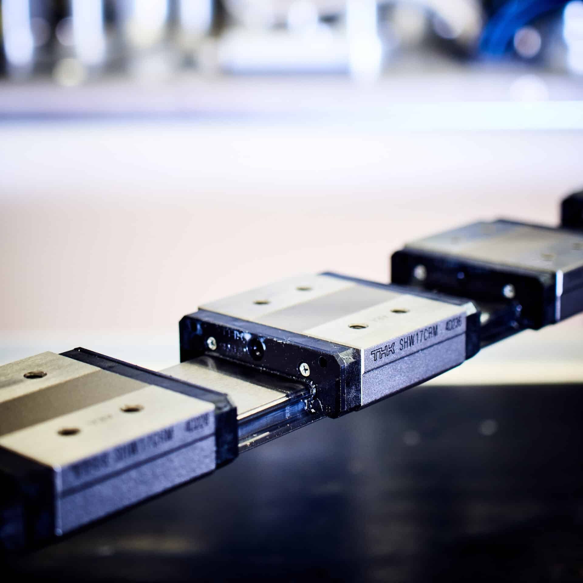
For accurate positioning, both the rail and the carriage have a reference side. This side is used as the fixed dimensional reference and is positioned against the reference surface, locating shoulder or reference edge of the machine bed. A line on the underside of the profile rail guide indicates the reference side. On the carriage, the reference side is located on the side opposite the laser-engraved THK logo.
The reference edge on the machine bed helps to position the guide rail accurately and assists in absorbing lateral forces. By mounting the correct reference sides against the reference surface, accurate and repeatable mechanical alignment can be achieved.
Installation sequence for a single profile rail guide with carriages
When installing a single profile rail guide, position the rail with its reference side against the reference surface of the machine bed. Then lightly tighten all mounting bolts by hand so that the rail can still be positioned.
Carefully press or clamp the rail against the reference surface of the machine frame. Then gradually tighten the bolts to the correct torque. Work from the centre of the rail towards the ends. This ensures that the rail is secured evenly and reduces the risk of unwanted stresses.
Next, mount the worktable or mounting plate onto the carriages. Initially tighten the carriage mounting bolts by hand. Move the carriages back and forth along the rail several times to allow the components to settle into position. Then tighten the bolts in a crosswise pattern to the specified torque to ensure an even distribution of pressure.
Aligning two parallel rails using a master rail and follower rail
In a parallel arrangement, one guide functions as the master rail and the second as the follower rail. First install the master rail according to the correct procedure, positioning it accurately against the reference surface and securing it in place.
The follower rail is then aligned relative to the master rail. Initially fit the follower rail hand-tight and then mount the upper mounting plate onto the carriages of both rails. By moving the worktable or mounting plate back and forth over the full stroke length, the follower rail can position itself more accurately relative to the master rail.
The bolts of the follower rail are then gradually tightened to the correct torque. In many situations, consistent running resistance over the entire travel is a good indication that the installation has been completed without excessive internal stress. For applications with higher precision requirements, the follower rail can additionally be checked using a dial indicator.
Discover profile rails at LM Systems
Checking the installation with a dial indicator
When the construction has high precision requirements, the alignment should be checked using a dial indicator. In practice, this process is used to verify the alignment accurately.
To check parallelism, mount the dial indicator on the carriage of the master rail. Position the probe of the dial indicator against the side of the follower rail. Then move the system over its full length to identify any deviations in parallelism.
To check straightness, position the probe so that it measures along the top surface of the rail over its full length. The height difference between two guide tracks can be measured by mounting the dial indicator on the carriage of the master rail and positioning the probe on the carriage of the follower rail.
This makes it possible to determine whether incorrect installation or an inaccurately machined machine bed could result in additional internal stresses.
Using shims to correct dimensional deviations
Shimming is required when the mounting surface is not sufficiently accurate to align the rails correctly in a parallel installation. Shims can be used to correct small deviations in parallelism, straightness or height.
Use thin, flat and accurately manufactured shims for this purpose. The shims must be large enough to transfer the forces from the rail effectively to the machine frame. If the contact area is too small, local stresses or misalignment may occur. Shimming must therefore be carried out carefully and should always be assessed in relation to the overall alignment of the guide system.
Installing and aligning joined profile rails
For long strokes, joined rail lengths can be used. Within our knowledge base, these are also referred to as LT rails. The ends of these rail segments are precision-machined and marked with identification codes. These codes must be followed during installation to ensure that the rail sections are positioned in the correct sequence. Segments with corresponding markings, such as A1 against A1 and A2 against A2, must be mounted against each other.
First position the individual segments hand-tight against the reference surface of the machine bed. Here too, work from the centre towards the ends while gradually tightening the bolts to the correct torque.
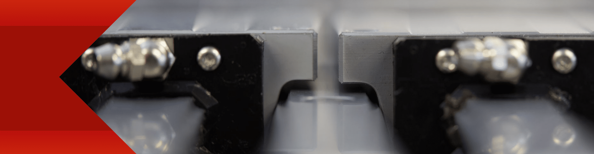
Ensure that the joined sections fit tightly against each other so that the transition cannot be felt when the carriage moves across the joint. One practical method is to position the carriage stationary over the joint during installation. This allows the transition between the rail sections to be aligned accurately before the bolts are finally tightened.
Would you like to take your design to the next level, or are you facing a technical problem that you cannot resolve yourself? Our engineers are ready to calculate your application and configure the optimal linear motion solution. Contact us to arrange a consultation with our specialists.