

The correct preload of a ball guide significantly determines the positioning accuracy, rigidity, and travel characteristics of a machine axis. Selecting a specific preload always depends on the application and begins with an understanding of internal clearance and the required mechanical properties.
Negative Clearance
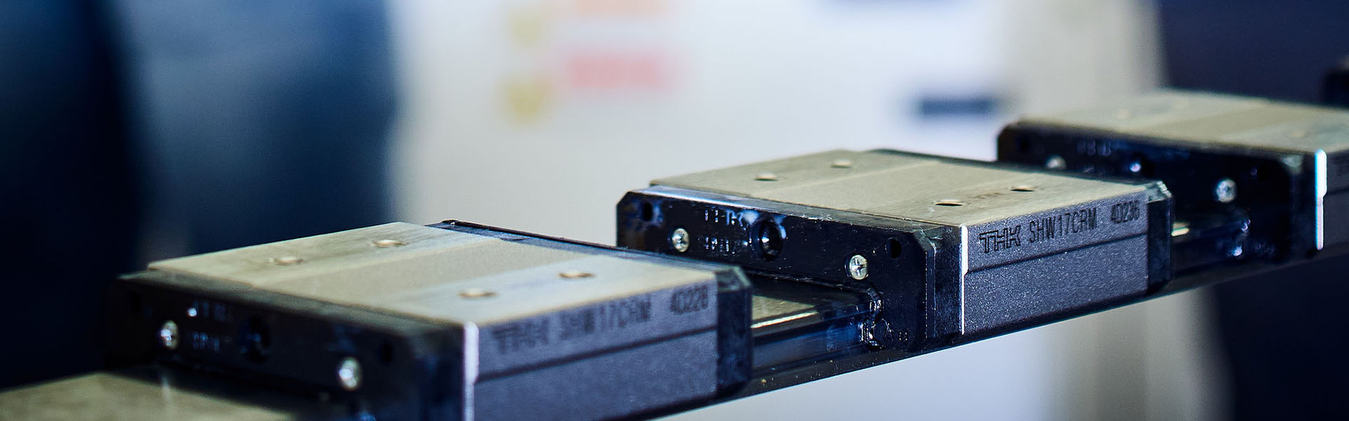
Most ball guides are designed with negative clearance. This means that, by default, there is already a degree of light preload. This preload is created by the ratio between the ball size and the raceway, ensuring stable and reproducible travel behavior. Depending on the application, this preload can be adjusted by changing the balls at the micrometer level, in increments of thousandths of a millimeter.
Light and Medium Preload for Ball Guides
By adjusting the ball size, a light preload can be achieved, designated as C1. This version combines low frictional resistance with improved rigidity and allows carriages to be interchanged on the same rail. This is ideal for applications where accuracy is important, but flexibility in assembly and maintenance remains a priority.
For higher, medium preload, the configuration is referred to as C0. In this case, the rail and carriage are matched as a set through specific ball selection. Consequently, the carriages are no longer interchangeable. This configuration is used when higher demands are placed on rigidity and positioning accuracy.
-
C1: Light preload, interchangeable carriages, low rolling resistance.
-
C0: Medium preload, rail and carriage matched as a set, higher rigidity.
Measuring Preload in Ball Guides
The achieved preload for a ball guide is verified by measuring the rolling resistance. This is performed using a force transducer in combination with a measuring amplifier. By measuring the force required to move the carriage, insight is gained into the actual preload. This methodology makes it possible to adjust the preload in a reproducible and controlled manner, tailored to the application.
As preload increases, the requirements for the mounting surface also become more stringent. A higher preload means that deviations in flatness, parallelism, or torsion directly impact rolling resistance and wear. The mounting surface must therefore meet prescribed accuracy standards to prevent unwanted stresses within the guide.
Applications with High Rigidity Requirements
In machines where high rigidity and minimal deformation are required—such as 3D measuring machines—preloaded carriages are utilized intentionally. The higher preload contributes to a stable measuring axis and limits microscopic displacements under load. The final choice of preload always results from the combination of accuracy requirements, loads, and mounting conditions.
LM Systems delivers every guidance system custom-configured with the correct preload for your application. Would you like to know which configuration best suits your machine? Feel free to contact us for technical advice.